How Is It Different From GAN? Are You Familiar With The Image Generation Model NeRF?
3 main points
✔️ NeRF is a novel viewpoint image generation network.
✔️ Input of NeRF is 5D (x,y,z of spatial coordinate and θ,φ of viewpoint) and output is volume density (≒transparency) and radiance (≒RGB color).
✔️ We succeeded in obtaining a novel viewpoint image of an object with a more complex shape than before by NeRF.
NeRF: Representing Scenes as Neural Radiance Fields for View Synthesis
written by Ben Mildenhall, Pratul P. Srinivasan, Matthew Tancik, Jonathan T. Barron, Ravi Ramamoorthi, Ren Ng
(Submitted on 19 Mar 2020 (v1), last revised 3 Aug 2020 (this version, v2))
Comments: ECCV 2020
Subjects: Computer Vision and Pattern Recognition (cs.CV); Graphics (cs.GR)
code:

The images used in this article are from the paper, the introductory slides, or were created based on them.
outline
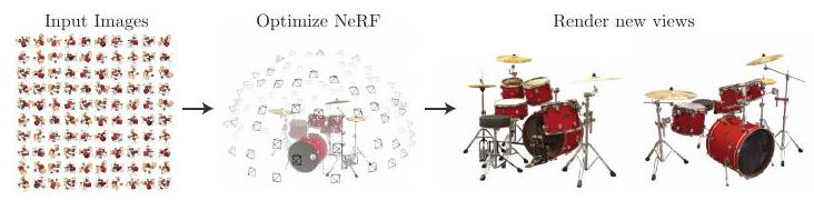
First, watch the animation below to get an idea of the "New Perspective Image Generation".

The animation above is generated by NeRF, where the new viewpoint is the camera position and the new viewpoint image generation is the answer to the question "What image do we get when we look at the object from a certain position? The animation above is generated by NeRF.
The easiest way to create the above animation is to take a series of pictures while moving the camera (just like a movie), that is, by taking a series of pictures of an object while changing the viewpoint little by little, the object appears to be viewed in three dimensions. However, in NeRF, you can only shoot from three viewpoints (front, side, and back), and you can get images from "diagonally forward" and "diagonally backward" which are "not shot" in between. This is called "novel view" image generation.
first of all
This research addresses a longstanding problem in view synthesis (view synthesis) by using neural networks to optimize the parameters of the image representation.
The authors represent a static scene as a continuous 5-dimensional function that outputs the radiance (with direction θ, φ) and density at each point (x, y, z) in space This function acts like a differential opacity that controls how much luminosity (i.e. how bright) is stored by the rays passing through each point.
In our method, we transform the five-dimensional variables (x, y, z, θ, φ) into volume density and RGB color by regression using a Multilayer perceptron (MLP) without convolutional layers MLP regression is simple and easy to use method.
In the "3 essentials" section, I wrote "volume density (≈transparency)" and "radiance (≈RGB color)", but this is not accurate. volume density is a variable that is necessary when rendering, and it controls the diffusion, reflection, etc. of light passing through an object. I wrote "transparency" for simplicity, but think of it as a factor that interacts with light, and "emitted radiance" is not equal to RGB color. It is not equal to RGB color, but refers to the light emitted from a point on the surface of an object (the sum of the point's light source and the reflected or transmitted light from the surroundings), and should be understood as a variable necessary for rendering. It should be understood as a variable necessary for rendering.
To obtain the neural radiance field (NeRF), which is the output of the regression, the experiments in this study were conducted as follows.
- Move the camera to various positions in space and record the coordinates of the camera.
- The above camera position and the associated direction of gaze are the inputs to the neural network, and the images from that position are the outputs (teachers).
- The process of generating a 2D image from color and luminance is based on classical volume rendering, which is differentiable and can be optimized by a neural network.
Through these steps, the model is optimized by actually minimizing the difference between the observed image and the output result; the protocol flow is shown below.
related research
A recent promising direction in this field is the encoding of scenes using MLP, but it has not been able to reproduce realistic scenes with complex shapes. ShapeNet is known for the representation of 3D shapes, but the difficulty of aligning teacher data in the first place has been a barrier to research. The ShapeNet is a new method for 3D shape representation.
Later, by formulating a differentiable rendering function, it became possible to optimize the 3D neural implicit shape representation using only 2D images. Niemeyer et al. considered the object surface as a 3D occupancy field, calculated the surface intersection of each ray using a numerical method, and calculated it exactly by implicit The position of the intersection of each ray was then used as input to the neural 3D texture to predict the diffuse color at that point. Using the neural 3D texture, Sitzmann et al. proposed a differentiable rendering function that outputs feature vectors and RGB colors in continuous 3D coordinates.
Neural Radiance Field Scene Representation
The authors represent the continuous scene as a five-dimensional vector-valued function, whose inputs are coordinates (x, y, z) and line of sight (θ, φ) and whose outputs are color (r, g, b) and volume density σ.
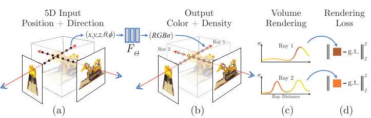
The above figure shows an overview of the scene representation and differentiable rendering using NeRF: 5-dimensional inputs (position and line of sight) are used to compose an image along the camera ray (camera ray, represented by the eye and red arrow in the figure). The five variables (x, y, z, θ, φ) are input to MLP (F_Θ), which outputs RGB color and volume density (R, G, B, σ).
Volume rendering with Radiance Field
The volume density σ(x) can be interpreted as the differential probability that a particle with one ray infinitesimal ends up at point x.

C(r) is the predicted color of the camera ray r(t) with proximal t_n and distal t_f. The function T(t) is the probability that the ray will travel from t_n to t_f without colliding with other particles, expressed as the cumulative transmission along the ray To render a view from a continuous NeRF (neural radiance field) the desired virtual camera must be integrated over each pixel it passes through.
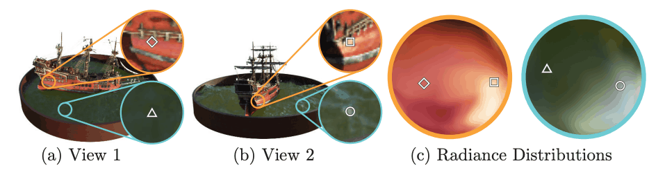
The above figure shows an example that the color of the same point changes when the viewpoint is changed. The color changes when the line of sight changes, even at the same coordinates.
Optimization of Neural Radiance Field
We discussed rendering in the previous section, but in practice, it is not enough to achieve state-of-the-art (SOTA, the highest quality). In the previous section, xyzθφ was input to the network F_Θ, which is replaced by the following composite function.
![]()
F'_Θ is a multilayer perceptron.
![]()
γ is a high-frequency function expressed as above.

Similarly, C simplifies the above.
result
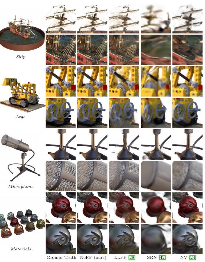
Comparison with Neural Volumes (NV), Scene Representation Networks (SRN), and Local Light Field Fusion (LLFF). All of the images are distorted and have more details when compared to NeRF.
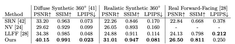
The table above summarizes the comparison results.


Each index is a loss function, which compares the GT and the generated image from a certain point of view: PSNR and SSIM indicate that the larger the better, and LPIPS indicates that the smaller the better This shows that NeRF outperforms all existing methods.
Conclusion.
In this work, the authors tackled the problem of existing MLPs representing objects and scenes as continuous functions and succeeded in representing the scene as a 5D Neural radiance field. This has allowed us to advance the graphics pipeline to generate new viewpoint images from real-world objects.


Categories related to this article
